Hi, Stefan and I thought about as we show you wireless technology times or teach
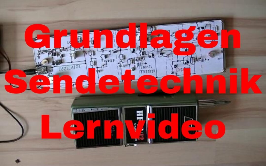
can As an example you see here this very
old radio which of course is much more complex than the circuits
we now show you, we are just scratching a little on the surface but it just will virtually a, yes, inspiration
provide for their own projects and understanding wireless technology contribute a little. We have made two boards, one
a circuit board with transmission technology there still are those little additional Platinchen
with it, we have a low pass, a High pass and band pass on that later
more and there is still an external antenna. On the receiver side her in a
other video see, because we do it in 2 videos because it would be too much else we have a board with different receivers
Circuits built up you simply a to show little what types of receivers
there are What are the advantages and disadvantages of the
Receivers and how does it work.
In the following clip we start now
for you have clicked the send video, with the transmitter video and then let's start
with the oscillator. and now we tell you the oscillator the oscillator is actually, so you can
say the most important part of the sender because he even produced times the frequency to
which is then transmit the information. there are different types of oscillators
various circuits, we limit us now on the so-called Clap oscillator
of a modification of the Colpitts oscillator is. these are now just the name of inventors
these circuits, we want the easy look at it. there are the so-called crystal oscillator
her yes see here this quartz crystal oscillator has the advantage that it has a very stable
Frequency generated which does not change, as we later test that the frequency
may change, but of course logically the disadvantage that you tied to a frequency
are, you have only a single frequency, the you can use it, and that's a bit
limited.
Then there is the LC oscillator, is there
the frequency determined by a coil, Coil can for example be such a coil
you can adjust as you can then Take a screwdriver and you can
then around turn, or even a fixed inductance, which is a coil which has a fixed value
which can not be adjusted. Furthermore, the frequency is determined, if
one parallel to the whole a capacitor switches that can here a capacitor having
be a fixed value, then you have again a fixed frequency that does not disfigure their
can, or even a so-called "trimming capacitor".
Set the radio to the frequency you have
but a variable capacitor. The difference between a trimmer capacitor
and a variable capacitor is that the Trimming capacitor on the circuit board soldered
and you can adjust it a few times, but should not provide lasting around it,
and the variable capacitor on the radio because you know her yes, the one can be adjusted more often.
Thus, the oscillator is already set up,
the circuit is also supplied with voltage, Then we look at the first thing once the quartz
Oscillator on. When crystal oscillator is now the quartz,
of 1 Mhz crystal of base connected to ground. The signal of the oscillator on the radio
to transfer I connect another now Circuit part we do not yet discuss,
Take him just once as "given" back such as a buffer or simply a part of the
the signal loops through, and then have we here an external antenna, and the external
Antenna then transmits our signal just in the so that we can receive the whole radio. now I just watch how the rum
must put up with, you have to plug in so rum because it is not very easy, so then we ask the great times of radio
Eflose I tried a bit have and am also very excited to
1 is a Mhz and now we have 1 Mhz so if I now let the oscillator so
and for a while waiting he will not adjust.
We can, for example, once the halogen lamp
take the Eflose has since a halogen Light with him, and keep the halogen lamp
We now times back to the transistor. Must of course the whole thing a bit neater
make it here is not so chaotic, so, that the halogen lamp is lit and heated
the transistor. Characterized that the transistor is heated,
the frequency is normally in the long term adjust.
So you have a frequency set to
For example you want to 1200 Khz provide uh Send and the room is warm it because
Summer is, it heats the room and on Suddenly your transmitter has moved on
a different frequency, it will not work more, and what's going on … But as you already heard on the radio, so you
hears actually that nothing changes, from noise forth, the frequency remains stable
and we could sit here for so long now remain until the batteries are empty, and
Nothing would adjust. Ok, you can turn off the lamp again Next, there is the so-called LC oscillator. The LC oscillator has the advantage that one
can adjust the frequency, so I can any frequency in the medium wave band
as part of the circuit is set.
I now ask times the frequency, say
Let's 700, now I can do a straight read little bad because I from the lamp
am still dazzled, I think that is 760, so let's set up so 800 Khz. And now I can here with the screwdriver
turning on the spool or on the variable capacitor, I turn times on the rotary capacitor … the
is not now because we are still too high Total inductance because I have here
a coil and another coil and when I turn both coils in series added
is its inductance. So I close now just an hour
thus I just have a smaller Inductance. A smaller inductor results in a higher
Frequency. And now I would have to actually be able
set to be the 800 Khz … ok it works not, that is the demonstration effect … Sorry it does not work we look for a lower frequency as it can
I perform better, works here it, let's say we are on 640 Khz, here
can I now the frequency with the variable capacitor adjust, you already hear it over here
going I must still seek the exact frequency …
ah here about 770 Khz, now, so I can go through
the sink adjust the frequency and I can by the variable capacitor, the
adjust frequency, um by the trimmer capacitor which is now the advantage of the LC oscillator
you can check out any frequency in choose medium wave band and can then
send on this frequency if we do the test with the lamp again
do this you need to turn up the volume Radio times so you can hear it better Yes, turn on the lamp again so that we now have to wait a bit but if you listen closely you will notice
that with time the noise from the noise change if we had a frequency counter, the
unfortunately we do not have, so do not for this Circuit now, would it even better
hear or not hear better, one would see it in number can still directly to the transistor to the
Housing that will calm a bit hot be the transistor that it might quite like
when it is hot, at least the here my fingers are also hot ..
Oh so …. But you listen to it now that it is a
little hisses differently the changes already you can also times to the ceramic capacitor
go here yes, effect is already there but is not
so strong, you can the video even rewind and listen as there
rushes, it is a light hiss now been added because the frequency might
adjusted to 10 Khz but has if the whole Now, of course, would be a bit extreme
then the frequency would of course correspondingly further adjusted. So the other option out there, and
those are unwanted effects that we want yes on the frequency on which we do not send
that the frequency changes again but we want that the frequency stays that way. The other effect would be if the
Voltage adjusted. We supply the transmitter or oscillator,
we provide now with a bit more than 12 volts, if we now replace the 12 Volt
by 9 Volt, so supposing the battery goes blank because we have less power,
then the frequency also adjusted. In the case, unfortunately, you hear even a
soft hiss as this oscillator itself but is very stable depending on how
strong, the frequency and adjusted as large these differences may be the
Frequency in a range so adjusted that the part is no longer usable.
So it can be no longer really
use if it is adjusted continuously um so then up here we do not have a component
this is a so-called capacitance diode. A capacitance diode is something like
as our trimmer capacitor or our coil actually more like the trimmer capacitor
in the case when you look at it closely but they has the same effect as the coil when
I have a voltage on the capacitance diode investing can I adjust their capacity
since the capacitance diode to the whole parallel So resonant circuit is I can with a voltage
detune the resonant circuit at the capacitance diode and thus adjust the transmission frequency. The whole thing is called VCO or Voltage Controlled
Oscillator, voltage controlled oscillator, something you can find for example in the CB radio
in the PLL, since a capacitance diode set the frequency and also at this
Capacitance diode in the cheapest case modulation fed us a frequency change
to have. Or in your FM radio where the frequency
can digitally adjust the display, is there also as a capacitance diode in it.
In our case, we are having this capacitance diode
times before and indeed I clamp now a potentiometer
these capacitance diode and when I think of This Poti turn then can I the frequency
adjust and unfortunately you only hear one bit bad though radio already on the
highest volume is perhaps going better now You might see it on the Tune LED that
that goes on or off and can now Eflose time measure the voltage then we can
prove with its sophisticated measuring device that is
really very high so it makes a quality impression, just take mass
Here on the lower pin at the top of the resistor, so No on the other side, on the other
page ah there since a voltage and now when I mete
this tension pretending, we have 4.6 volts, if I disguise the voltage then is happening
already something, you just did not hear the frequency is now changing a bit upwards it has no contact or clever? Now we had just 4 volts now 9 volts, if I but the tension
Now contrast down then changes the capacity to become larger, more
pf, and thereby the frequency changes by below, so if I now the tension here
again disguise, especially in the area noted her, that is between 0.2 and 2 volts
I can adjust the frequency here with this capacity diode.
And that's basically the difference of
an LC oscillator and the X valley oscillator, LC has an intentionally adjustable frequency
always a firm during the X-Tal oscillator Frequency has. Ok, you can do the meter back away Now we have something that we'll show you
can we now have the frequency set in the radio, we now have our transmission frequency
set on the we just send now we will charge the oscillator. This can happen in the simplest case by
that we now connect an antenna. So now but the following happens, must now
I even unplug the antenna here because we do not have something else in that we
now sends an LC oscillator use now produce these and the coil, the two
a magnetic field which is of the ferrite the radio resumes and receive
becomes.
If we now go forth and Oscillator
strain, the output of the oscillator, which here is the emitter if we now the burden
then jumps the frequency. So, load off, the signal is again
there jumps to load and Frequency away, which is another drawback of the LC oscillator. Now if we but take the crystal oscillator,
I need to change the batteries because the quartz oscillator by the circuit design
very sophisticated in its operating voltage is if you will … If we take the crystal oscillator,
the 1 MHz oscillator then we have two effects, only times the capacitance diode has no effect
more because it is not in the circuit and even if it were in the circuit
would change the frequency so minimal that we do not notice it ..
In the oscillator now yes this is now a bit hard to film I have to reconnect the antenna should now actually a signal to 1
have Mhz, maybe this is a bad contact or so ah there is a signal, as is now the signal
from the oscillator and if we bill now that, it makes ok
no sense because we now shorting do but what I want to show you would
if we weigh this oscillator now then the frequency is not adjusted, we
get exactly the opposite effect but I can show something, I can radio
close then follow the board act the conductor tracks as a transmitting antenna and when
I now burdening the oscillator then stops her that it makes crackling sounds so but the frequency does not shift so if you have such an oscillator of
should be on a frequency if and builds her best a crystal oscillator So now it goes for modulation, one
can indeed from an oscillator already a complete stations relied on when it is very
just want to make and if you do not wants to invest many parts can be a
build stations as at Efloses FM Transmitter yes you probably already seen.
Now that's another topic because
we use here amplitude modulation and at Efloses channels we use frequency modulation. so now so we have the station up here
and the signal is also sent now can we feed modulation here. Modulation is a yes if you will
sound technical term of a little intelligent but not much behind it,
there is nothing else like we eat now Music one from a sound source in the transmitter,
or in the oscillator. For this I connect the NF output Efloses Walkmans
with the f input my circuit. So now I've got a voltage divider
made up of two resistors, I have above a rather low resistance
with 1.2 Kohm and down a fairly high impedance here Resistor with 22 KOhm if I now between
these two resistors NF feeder, So music feeder then I change the
Voltage across the resistors, if I can the half-wave is positive Add transmit power
by the music and when the half wave negative is I take away transmission power, thereby getting
I amplitude modulation.
We have since later have a nice
Image for you. Ok I press now just play and
hope that the volume fits and then you can hear the music from here
Efloses cassette on central shaft so that is now clean amplitude modulation,
I can radio exactly to the frequency Setting up and hear this modulation. Now there is still the possibility that we
the whole with the LC oscillator do, then but the following happens, we get a
little problems, unfortunately I can not do that so well in the video show as I had before
on the circuit because I change so many had and the effect, although already there but
not as much as I wanted to bring him now we have the free-running oscillator
we saw earlier had the disguises himself and now dine here my NF one, so I
the frequency may be adjusted as desired, Here is the signal we already hear
Music, I can adjust the frequency again if I want Only what we have now for an effect,
we have frequency modulation, that is I have the radio always a bit wrong
adjust, not to the right frequency but always a bit beside else
the modulation bad Unfortunately, this works only so so
that you can hear it now distorted you can hear clearly that it distorted but if
I'm wrong again so adjusting the radio next to the frequency then it goes again which is a further disadvantage of this simple
Oscillators when one modulates generated one frequency modulation and that is because
that here in the transistor between base and Emitters such as a variable capacitance diode is so
there's a kind of capacity led inside and when I change the voltage then change
I, the voltage at the base and thus the Capacity and if you whole time back
pursuing higher than many capacitors of this Transistor yes parallel to our coil and
thus this frequency modulation arises.
While there are tricks how to handle the
but usually at a free running Oscillator amplitude modulation has nothing
lost. ok, that it was now for the Chapter Oscillators. We have here a chart for you and that is about how this amplitude modulation
is working. If you now times a microphone or
Connect cassette recorder to your oscilloscope would you then maybe you will very quickly
but given time you can your oscilloscope pause as in a digital, a
received waveform. We have different frequencies and
We also have different amplitudes, the frequency is the distance from here to
Here, the amplitude and the distance of here to here above, or even from the center line
up to here, or from the center line to by below. and what now as an AM transmitter power, so a
Medium wave transmitters or shortwave radio, or the old CB radio from Eflose it
takes the AC voltage of our NF and it regulates its transmission power.
We would have here now in the middle where this
black line is 10 milli watts when we but now have a half-wave of our
Language that goes into the minus-voltage range So, for example, minus 1 volt then controls
of the transmission power down to 5 milli Watt and now the whole thing here very quickly
back into positive territory at plus 1 Volt because it regulates the transmission power again
up to 10 milli Watt, and you see here over there I drew it again,
since the half-wave is not as high as we then we follow in positive
Area only 12 milli Watt because it is not so is noisy and milli in the negative region 8
Watt because there is even less further down.
So when is the modulation always the
Transmit power in response to the fed Signal changes, the frequency, ie the
Distance from here to here or from here to here remains the same. Since there are two power ratings, there are
the so-called ERP performance, the performance view your transmitter to a measuring device
would if you connect it to the meter, pushes her to send then you have a
Power to the meter and that is the ERP Power, which is 10 milli Watt in the case,
because it is the center, which is the power if you do not speak into the microphone or not
feeds music. if you now speak into the microphone then changes
something that the transmission power and this information is called PEP performance.
Ok, but those are the basics such as
an AM transmitter, such as an AM transmission is working. Now we tell you about buffer
amplifier The buffer amplifier is a nice and
smart circuit, the one additional way the oscillator normally to build. we have seen before, when we the
Oscillator burden then there are these unwanted Frequency hopping which we do not have
want. so, but we still want the signal from
Using our oscillator somehow, maybe We want to connect an antenna, maybe
we want something to drive it and why there are the so-called buffer amplifier.
The buffer amplifier receives the signal from the
Oscillator and forwards if you like want while ensuring that this
if you now loads the output of the buffer, for that I must go to this terminal to make out of here,
the part that is because not yet there, but if one loads the output of the buffer,
I'm now just take a short to its output down, then nothing happens
the frequency remains absolutely stable because it no longer interested because the oscillator
Now the transistor has quasi thereby work that we short-circuit its output.
This makes the buffer amplifier, you can hear
it, too, now that's a bit hard down when I position the radio there,
yes you can hear it a bit poor but one would theoretically also hear a clicking noise,
at least, indeed this is now the second take, before you've heard it, but has previously
what else not fit, anyway, So you, the buffer amplifiers already see
would also signal to the output stage further or to the power amplifiers driving when I now
this driver connect then you hear it, so we hear a clicking sound but the frequency
remains stable, so the light will stay Tune and when I plug now here the
Tune lights dim or go depending on the position the radio even out. and nothing else makes the buffer, it makes
easy for us to output the signal forward the final stage or the final stages Driver
can without the oscillator its frequency changes.
Now, there are still a neat trick
one can make, because if we are the Watch here once, we have now
a collector circuit, that is, the collector the transistor is right on Plus and
our "load circle" in the case of resistance is located in the emitter to ground. If we have now look at this then
We here a resistance of the working determined, but we can also now produces
can go and have an additional Resistance to feed an external signal
and if we then the operating properly we can define the gain
of this transistor a little change, So not the physical gain
but the gain from this Circuit, we can change a bit
and if we then feed our NF then we have nothing more as an amplitude
Modulator.
By the way you can see here that I arrows here
have made, with an arrow pointing to the outside and below an arrow inside,
of professional equipment I have also seen is quite logical, the arrow of where
says because it goes in there feeds you a signal in and the arrow of where says
as it goes out there is a signal Out. Good to run the front we're now
times the external antenna to this inductive Antenna for inductive transmissions
yes in principle theoretically legal, I have me at least from the Federal Network Agency by
confirm e-mail, um so Now we have again our NF signal
I put now here on NF input of this modulator, and it's nothing to what we now
would have to make, we would have with the potentiometer set the correct operating point. Only when the working right, so the
Voltage range by the transistor's Gain, the amplifier circuit their
may change as reinforcement works it, and I now turn here simply to the
Poti and have very good modulation and another
which now arises effect, I do not even a bit quieter, another effect of
is now created, we can now on the radio turn times and now we have really clean amplitudes
Modulation although we still have the advantage that we have adjusted our rate
can.
You may wonder why we the
gone frequency range here so far down are, that's because we have the next
have prepared attempt. but so much to the buffer amplifier, so
the buffer amplifier do you need if you uncouple the signal from your oscillator
want and then just want to pass on. is still a peculiarity of this circuit
that the collector circuit a voltage only Gain of 1, that is, if you
50 mV level at your oscillator then have only 50 mV come from this circuit
also out again, which is obviously not so practical. Since there is the emitter circuit since
then the emitter is connected to ground and between the collector and the quasi Plus
Load resistor, which has a very high Voltage gain because you can then
perhaps with 50 mV input voltage already a few VPP, so volts peak to peak at the output
to reach. However, the collector circuit has the
Advantage that it is highly resistive, ie they are not burdened your oscillator very strong
while the emitter circuit a very low and heavily burdened your oscillator. Usually one takes for something but
the collector circuit forth as they simply is very well suited for buffering purposes.
Ok that's it now for Chapter buffer. Now we come to the final stages Driver The output stages for driver is necessary
the power that comes out of your buffer again to strengthen a bit since
the performance of the buffer is not necessarily strong and they then for the output stage
adapt. I now have a lot of parts here already
times before but the wired for video are not important, I have the final stage
wired and I connected the antenna but that's not important now. It is important that we here the final stages Driver
have and here we now have an emitter Circuit. I do actually show the stylus The emitter is now connected to ground
and the collector we have a resonant circuit. but usually it is because her here
now see that we have a coil and a adjustable capacitor which are parallel,
that this capacitor is not available, we have only the coil and, together with the
forming capacitor goes to the output stage the one, indeed, a resonant circuit, so a
Series resonant circuit, and thereby the impedance customized.
We have above an impedance of perhaps
but 1 Kohm and the amplifier has an impedance of 50 ohms at its input and through the
Coil and capacitor can be the whole then adjust so that the very maximum performance
is transmitted in the output stage and thereby the amplifier output the highest transmit power
Has. That you might have seen before,
CB radio the same exists, since there is then such transformers to be set
can and as you can when the poorly matched are pick out only 1 watt and if you
well aligns maybe even 4 Watt depending on. And here we have designed a circuit,
I have here a transformer I Syndicate can I put here the radio out
Tune the LED is off and we also hear that but it rushes if I comparisons the transformer
can I adjust the amplifier to the advantage So the RF power amplifiers driver suits me then
quasi the amplifier to the rest of the circuit and I'm now just that
here now has no function that could we do actually get out, which do
I now times and thus should see her that if I turn to the transformer now that
then the Tune LED to go when I him get feedback and we have a signal.
I'm doing now with the other hand so
you can see the better. So you can hear the noise quieter
is and you can see perhaps that is rather dark, but you can see that the Tune
LED's going on if I disguise it again goes it out again, but you can already see with these
Amplifiers transformer driver, so the final stages Transformer and the driver I can, the output stage
to my advantage, so to the oscillator I adapt and buffers and such a good
radiated power then in effect.
Naturally one way now with the oscilloscope
even to the last Milli Watt, I know not whether we here at Milli Watt or
talk microwatts because the whole is very weak as it is only a model, could it anyway
the last microwatt still Syndicate. ok, that it was now for the power amplifiers driving,
I hope it brought you in what. and now we come to the final stage The output stage is also a very important part
your transmitter. what brings you because if you an oscillator have perhaps one
has half a Milli Watt transmitter power, you want but send a few kilometers and can
but not so far because you send only as have little power, then we need the
Final stage. Because of all the other circuit parts
together with the final stage we get a Output power of perhaps 0.5 Watt,
1 watt depending on how we interpret that.
At the final stage, there are various circuit
Versions, there is the so-called Class C Final stage. The class C amplifier works so that
a positive half wave of the power amplifiers driving comes, the transistor becomes conductive and
invites energy into that coil up here purely and then when the transistor turns off then
this transistor makes a short circuit to ground and thereby flows via these
Diode, but this may also be another component be back in a negative half-cycle and emptied
the condenser and so it goes games back and forth.
Your will see the class as soon as I C
Final stage now activate as I diode we turn on a signal on the radio. Thus, the output stage is now activated and strengthened
the signal when I get out the jumper prefer we have no power and can not. Thus, a different type amplifiers available
is the so-called Class A amplifier. The class A power amplifier is simply a resistor
of base to plus or a resistance of Based on the collector. This resistance ensures that the transistor
is already conductive and then the transistor if he's just been conducting the RF signal
also increase. So I put times the Class A and we
see again that we have a signal Now what's not so good with the jumper
because they do not want a bad mood.
But you can already see that it somehow because it
is that it'll work. Well, who is not it clever, that would have
one might somehow try to it to get him to go, but we need
later. So now there are still a few details to
These power amplifiers for the Class A output stage kann Musik verstärken, dazu müssen wir jetzt
ein bisschen was um verdrahten und wir sehen uns dann wieder im nächsten Clip. Jetzt kommen wir zur Endstufe Und zwar nochmal zur Endstufe, es geht darum,
um Linearität. Was ist denn jetzt der Fall wenn ihr ein Signal
habt das bereits moduliert ist und ihr wollt das jetzt weiter verstärken, nun dafür nimmt
man normalerweise eine Klasse A Endstufe im einfachsten Fall, im Luxus Fall nehmt ihr
eine sehr komplizierte Schaltung mir sehr vielen Übertragern, 2 Transistoren im AB
Betrieb aber für einen einfachen Verstärker nehmt ihr eine Klasse A Schaltung denn diese
Schaltung nimmt das Signal das kommt und wenn das Signal wie in der vorherigen Zeichnung
zu sehen war mehr Pegel hat macht die mehr Leistung, wenn es weniger Pegel hat macht
sie weniger Leistung, wir hören das auch hier sehr gut sobald ich jetzt den Jumper raus ziehe der
die Klasse A Funktion macht ist kein Signal mehr da, sobald ich ihn rein stecke geht es
again.
Jetzt müsst ihr aber was beachten, wenn ihr
bei dieser Endstufe zu viel Steuer Leistung macht also ihr wollt immer mehr Leistung und
mehr Leistung, wenn ihr zu viel Leistung macht dann verstärkt sie irgendwann nur noch das
reine HF Signal aber die Modulation schafft sie nicht mehr, wenn ihr euch das auf dem
Oszilloskop anschauen würdet hättet ihr einen Sinus der oben einfach quasi abgeschnitten
ist und dann wieder anfängt, also der obere Teil wird abgeschnitten und wenn ich jetzt
hier lauter mache am Radio und das mal mache, ich übersteuere jetzt die Endstufe, ich gebe
zu viel Leistung auf die Endstufe dann wird die Modulation sehr leise, es verzerrt
auch ein bisschen, wenn ich jetzt die Übersteuerung wieder entferne dann ist es wieder klar.
Wir können mal die Endstufe noch ideal anpassen
hier dann kann ich den Effekt vielleicht sogar noch stärker machen indem ich jetzt hier
an dem Trafo nochmal versuche die ideal anzupassen genau dann wird der Effekt noch stärker,
jetzt ist es richtig leise und auch schon sehr verzerrt wir haben fast keine AM mehr drin fast keine Modulation, Signal ist da, HF ist
da aber keine Modulation, wenn ich jetzt die Leistung wieder anpasse dass die Endstufe
nicht mehr übersteuert dann geht es wieder.
Und das ist es was ihr beachten müsst wenn
ihr so eine Endstufe habt, ihr könnt schon ein Signal verstärken aber sobald ihr zu
viel Leistung in die Endstufe gebt schafft sie es nicht mehr von der Linearität und
dann verzerrt es. Was ist denn jetzt wenn ich eine Klasse C
Endstufe habe, schauen wir mal es geht schon wie ihr hört aber es verzerrt
und jetzt gibt es hier noch einen Trick man kann die so anpassen dass es nicht verzerrt, zumindest ist es sehr
schwer aber es ist möglich also jetzt dass es eher schlecht ist muss ich mal leiser machen also es ist durchaus möglich mit einer Klasse
C Endstufe auch ein AM Signal zu verstärken allerdings habt ihr jetzt einen anderen Nachteil,
ihr könnt euch nur in einen gewissen Leistungs Rahmen bewegen und selbst wenn ihr jetzt einen
Endstufen Transistor drin habt, einen 2n2219 oder 2n3553 und ihr steuert den in Klasse
C an mit einen Hf Signal kann es sein dass ihr trotz eurer tollen Schaltung vielleicht
50 mW raus bekommt weil sobald ihr über diese 50 mW geht, geht der Transistor wieder in
eine Art Schaltbetrieb über und "frisst" wieder die Modulation.
Deswegen geht es mit der Klasse C Endstufe
auch ein moduliertes Signal zu verstärken aber es ist eher unüblich. Also, kurze Zusammenfassung, Klasse A Endstufe
könnt ihr euer Signal verstärken, Klasse C Endstufe könnt ihr euer Signal verstärken
aber tendenziell nur das reine HF Signal während ihr mit der Klasse A Endstufe auch die Modulation
verstärken könnt. Good. Im nächsten Kapitel schauen wir uns noch
den AM Modulator an den ich hier oben aufgebaut habe aber der macht eigentlich nicht so viel,
trotzdem können wir euch das mal zeigen. Ok, das war es jetzt zum Thema Endstufe. Jetzt haben wir noch was für euch aufgeschrieben
zu Klass A und Klass C Endstufen. Also hier haben wir mal die Klasse A Endstufe
und ihr könnt die Vorspannung der Basis entweder über einen Widerstand von Basis nach Plus
machen, ist aber eher unüblich weil das den Nachteil hat dass wenn sich die Betriebsspannung
ändert dass dann auch sich der Arbeitspunkt ändert und das wollt ihr nicht.
Oder ihr macht einen Widerstand zwischen Kollektor
und Basis also hier Kollektor und Basis, dann habt ihr eine sogenannte Spannungs Gegenkopplung,
dann stellt sich quasi der Arbeitspunkt immer automatisch in Abhängigkeit von eurer Spannung
nach. Der Vorteil der Klasse A Endstufe ist dass
sie eine hohe Verstärkung hat das heißt auch ein sehr schwaches Signal kann sie verstärken
und eine lineare Verstärkung, das habt ihr gerade gesehen dass man Musik damit quasi
übertragen kann. Ein großer Verstärkungsfaktor, sehr schwache
Signale werden verstärkt, sie hat ein sauberes Ausgangssignal, das heißt ihr habt da eine
Sinuswelle am Ausgang und eine geringe Steuerleistung ist möglich, wir haben jetzt ja hier so gut
wie gar keine Leistung auf unserer Platine die jetzt ein bisschen außerhalb der Kamera
ist, aber wir haben da keine Leistung, so gut wie, und trotzdem geht es ziemlich gut.
Der Nachteil ist aber dass ihr immer Stromverbrauch
habt das heißt es ist egal ob ihr da jetzt ein Signal angeschlossen habt von eurer Oszillator
Schaltung oder es nicht angeschlossen habt, die braucht immer Strom. Deswegen findet man diese Endstufe zwar schon
aber ihr findet sie meistens in so kleinen Sendern wie Funkkopfhörer Sender sowas oder
schwächeres CB Funkgerät, je nachdem. Die Endstufe in Klasse C findet ihr häufig
denn die hat viele Vorteile, sie hat eine hohe Effizienz, ich habe zwar hier mehr Vorteile
auf der Klasse A Seite geschrieben als auf der Klasse C Seite aber dieses hohe Effizienz
habe ich mit einen Ausrufezeichen versehen weil das wirklich ein sehr starker Kritikpunkt
ist den ihr habt hier einen Schaltbetrieb das heißt der Transistor ist entweder voll
leitend oder sperrt voll so braucht ihr nicht viel Kühlung dafür Ohne Eingangssignal haben wir 0 Watt Stromverbrauch
weil da nichts angesteuert wird Als Nachteil haben wir aber den geringen Verstärkungsfaktor,
ihr braucht schon einigermaßen Leistung um die gut durch zu schalten, das steht auch
hier, muss voll durchgesteuert werden und wir haben ein unsauberes Ausgangssignal da
der Transistor immer nur voll schaltet oder voll sperrt haben wir eigentlich eher eine
Art Rechteck am Ausgang die wir dann wieder weg filtern müssen.
Es gibt verschiedene Möglichkeiten die Klasse
C aufzubauen, üblicherweise wird sie mit einer Spule von Basis auf Masse aufgebaut,
es kann auch gerne, wie ihr im Trafo vorhin gesehen habt so eine art Trafo sein der das
dann irgendwie runter transformiert, man kann es aber auch mit einer Diode aufbauen oder
auch mit einen Widerstand alternativ. Und das sind einfach die Unterschiede zwischen
der Klasse A Endstufe und der Klasse C Endstufe. Eine richtige Endstufe wie ihr sie vielleicht
für das CB Funkgerät kaufen könnt, es gibt ja diese alten AM Geräte mit 0.5 Watt, man
darf ja heute mit bis zu 4 Watt senden auf AM, da gibt es dann ja vielleicht noch eine
Endstufe, die arbeiten gerne mal mit einer AB Endstufe aber das wäre jetzt ein richtig
großer Schaltplan deswegen haben wir die weg gelassen, es geht einfach nur um die Grundlagen
der Funktechnik.
Und das war jetzt der Unterschied zwischen
der Klasse A und der Klasse C Endstufe. Jetzt erklären wir euch noch den Kollektor
Strom Modulator Also wir haben die Endstufe weiterhin in Klasse
C geschalten was ja vorher funktioniert hat aber tendenziell eher so eine Bastel Lösung
war, es gibt aber eine Möglichkeit und so machen das zum Beispiel viele CB Funkgeräte,
Klasse C Endstufe trotzdem zu modulieren indem wir die Klasse C Endstufe das machen lassen
wofür sie Designt wurde, sie verstärkt einfach nur das HF Signal, nimmt keine Modulation
mit, die Modulation wird jetzt hier hinzu gefügt indem wir einfach die Spannungsversorgung
der Klasse C Endstufe ändern, mehr Spannung und weniger Spannung machen können wir natürlich
ihre Leistung beeinflussen, die Ausgangsleistung. Und das macht hier ein Transistor, ein PNP
Transistor, wir haben hier einen Widerstand drin der den Arbeitspunkt bestimmt und wir
speisen an Basis NF ein, dadurch kann ich steuern wie viel Spannung der Transistor von
Plus auf die Endstufe weiterleitet und dadurch haben wir wieder, wenn wir Musik einspeisen,
unsere Amplitudenmodulation.
Und auch eine sehr gute Tonqualität. Ok, die Musik kennt ihr wahrscheinlich schon
von Efloses Videos und jetzt habe ich euch das Ganze hier mal gezeichnet was hier was
macht, also wir haben hier das Schaltbild von der.. das Schaltbild vom Modulator und
wir haben hier verschiedene Bauteile. Erst einmal haben wir den Widerstand, der
bestimmt den Arbeitspunkt und wir wollen den Arbeitspunkt so bestimmen dass wenn ihr hier
die Spannung mit einen Voltmeter messt dass ihr hier die halbe Betriebsspannung habt. Also in dem Fall haben wir 12 Volt Versorgungsspannung
das heißt wir haben hier 6 Volt die vom Ausgang dieses Teils auf Masse messbar wären, also
zwischen Ausgang des Modulators und Sendeendstufe und Masse messt ihr 6 Volt.
Dann haben wir hier oberhalb der Sende Endstufe
einen Keramikkondensator und der blockt die HF Reste die eventuell von der Endstufe sonst
zurück fließen würden nach Masse weg denn ihr wollt im Modulator keine Hf haben denn
das ist sonst schlecht einfach gesagt, das verzerrt dann oder es pfeift ganz laut, es
funktioniert nicht. Dann haben wir hier am Eingang des Modulators
einen Kondensator, der blockt einfach die Gleichspannung ab denn wenn ihr sonst euren
Walkman anstecken würdet oder Mikrofon könnte es sein dass ihr den Arbeitspunkt verstellt
und hier nun die falsche Spannung habt und dann geht es nicht mehr, deswegen macht ihr
da einen Kondensator hin. Hier habe ich noch einen Kondensator systematisch
oder was heißt systematisch, symbolisch eingezeichnet, wenn ihr Probleme habt dass trotzdem irgendwie
Hf in eurer Endstufe ist, wenn ihr Probleme habt dass trotzdem irgendwie HF im Modulator
drin ist dann baut man einen Kondensator von Basis auf Emitter ein im Transistor denn der
blockt dann nochmal die HF weg und dann stört es nicht. Das merkt ihr dann dass Hf in dem Modulator
ist wenn eure Modulation verzerrt ist und sich dieses Geräusch dann ändert wenn ihr
die Antenne verändert, wenn ihr zum Beispiel zur Antenne hin fasst also mit der Hand in
die Nähe der Antenne kommt und dann vielleicht sogar ein Pfeifen einsetzt dann habt ihr Hf
im Modulator und dann könnt ihr diesen Block C einbauen.
Und generell ist dieser gesamten Schaltung
noch ein großer Elko parallel geschalten, der blockt einfach die NF denn bei stärkeren
Sendern haben wir hier ein paar Watt an Niederfrequenz die blockt er einfach ab dass die Spannungsquelle
nicht auch noch die Musik quasi wieder in die Spannungsquelle rein geht. Die alte Version von den alten Geräten da
haben sie es leichter gemacht, da haben sie einfach einen sogenannten Modulations Trafo
verwendet, das ist ein Trafo der hat auf der einen Seite vielleicht eine Impedanz von 8
Ohm und auf der anderen Seite vielleicht eine Impedanz von 1 KOhm und dadurch dass ich eben
die Musik herauf transformiere habe ich hier eine Gleichspannung die durch die Spule fließt
und einerseits die Endstufe mit Gleichspannung versorgt dass sie arbeiten kann, dann habe
ich hier wieder den Abblock Kondensator, den habe ich hier drüben schon beschriftet deswegen
habe ich es nicht nochmal beschriftet und jetzt haben wir aber die Gleichspannung
die von der NF also der Musik oder Sprache quasi überlagert wird und das ändert auch
wieder die Sendeleistung der Endstufe, die Leistung wird entweder zur Endstufe addiert
was mehr Sendeleistung macht oder sie wird subtrahiert was weniger Sendeleistung macht.
Und auch hier haben wir wieder diesen großen
Elko der wieder die NF abblockt falls hier viel Leistung ist dass die NF nicht zurück
auf die Batterie gibt und restliche Teile der Schaltung beeinflusst. Denn wenn ihr jetzt zum Beispiel die Nf bei
dem freischwingenden Oszillator auf der Betriebsspannung habt moduliert die NF ja wieder den Oszillator
und ihr habt wieder Frequenz Modulation. Ok, das war jetzt die Theorie wie man so einen
Modulator aufbaut um zum Beispiel eine Endstufe zu modulieren. So, wenn wir Klasse C Endstufen nehmen, besonderes
bei Klasse C dann haben wir noch eine ganze Menge an Oberwellen, doppelte, dreifache Frequenz
die die Endstufe noch mit macht. Wir wollen euch jetzt neben dem Tiefpass Filter
wollen wir euch auch noch andere Filter zeigen, natürlich macht ihr das nicht so dass ihr
diese Filter an die Endstufe anschließt, also den Tiefpass natürlich schon aber keinen
Hochpass oder Bandpass begrenzter Weise, normalerweise findet ihr diese Schaltungen im Oszillator
even Es gibt zum Beispiel Quarz Oszillatoren die
die Frequenz vervielfachen, da schwingt der Quarz auf 9 Mhz, wir wollen aber 27 Mhz also
verwenden wir dafür einen Bandpass, aber dazu später mehr.
Jetzt haben wir hier den Radio und wir haben
hier die Klasse C Endstufe aufgebaut und was wir jetzt mal vorführen wollen sind schon
mal Oberwellen. Nimmst du mal den Radio und gehst mal zur
Spule, da müsste man Musik hören gehst mal ganz nah an die Spule hin und suchst
einfach mal das Mittelwellen Band ab, ungefähr bei 522 Khz sowas bei 1 Mhz etwa haben wir das Signal noch mal und da haben wir den noch mal allerdings sehr
weak Man kann jetzt natürlich sagen, Cool, wir
senden auf mehreren Frequenzen gleichzeitig, das erhöht die Chance dass uns jemand zu
hört aber es gibt Leute die sich vielleicht gestört fühlen wenn wir alle möglichen
Frequenzen mit unserer Musik voll senden Deswegen gibt es den Tiefpass, ich habe das
jetzt mal als Modul aufgebaut und ihr werden auch sehen dass es wieder verkehrt ist, also
auf dem Kopf steht denn ich habe wie gesagt diese Platine in einen großen Tempo zusammen
gebaut um alles zu schaffen aber jetzt haben wir am Ausgang einen Tiefpass angeschlossen,
jetzt ist nicht nur der Effekt dass das Signal das wir jetzt haben wollen stärker ist sondern
wir haben jetzt auch die Oberwellen raus gefiltert, du kannst jetzt nochmal am Radio suchen Haben richtig viel Leistung Jetzt haben wir die Grundwelle, richtig stark
auf der Grundwelle, die wir haben wollen die erste Oberwelle, ganz schwach hört man
es noch ganz schwach die zweite Oberwelle ist so schwach dass man
sie gar nicht mehr her bekommt und die Erste ganz schwach und die Grundwelle ist richtig richtig stark richtig richtig starke Grundwelle ok, jetzt haben wir die anderen Filter noch,
bei denen ist es so dass man sie, wie gesagt, eigentlich in den vorderen Teil der Schaltung
hin baut, wir haben zum Beispiel einen Oszillator der auf 9 Mhz ist und wollen 27 Mhz also bauen
wir am Ausgang von dem Oszillator den Hochpass hin und definitiv nicht vor die Antenne Aber zum Vorführen was der Hochpass macht
werden wir das jetzt mal so machen, wie gesagt das Ganze aufgebaute Teil hier ist ja ein
Modell, obwohl wir hier ganz viele Stufen haben hat
dieser Sender vielleicht 0.1 mW , ich weiß nicht, irgend sowas also sehr wenig Sendeleistung aber trotzdem können wir ja vor führen was
ich zeigen will gut, ich tausche das Ganze jetzt aus So, jetzt zeigen wir mal den Hochpass Der Hochpass wird wie gesagt verwendet wenn
ihr zum Beispiel von einen 9 Mhz Quarz die 27 Mhz Oberwelle raus filtern wollt.
Ein Hochpass besteht natürlich aus ein bisschen
mehr als einer Spule und einen Kondensator aber die einfachste Schaltung besteht daraus. Ok, schauen wir mal am Radio Da sind wir auf 1.6 Der Oszillator schwingt aber nach wie vor
auf 522 Khz 1.6 haben wir jetzt ein starkes Signal, die
Lampe leuchtet dann gehen wir runter auf 1 Mhz ist es eher schwach ist schwach auf 1 Mhz und Grundwelle ist es noch viel schwächer umso präziser man diesen Filter auslegen
würde, also um so mehr Stufen er hätte umso schärfer wäre dieser Effekt Wir sehen schon, je höher die Frequenz wird
umso stärker wird das Signal 1 Mhz ganz schwach verglichen zur Grundwelle ist es stark aber
immer noch schwach Aber auf 1.6 ganz oben da leuchtet sogar das Licht, bei 1.6 Jetzt zeigen wir einen Bandpass Den Bandpass hat man zum Beispiel im Radio
beim ZF Filter oder im Radio bei der Vorselektion, im UKW Radio dass nur die UKW Frequenzen durch
kommen und nicht die Flugfunk Frequenzen aber wir haben auch einen Bandpass um unseren Mittelwellensender
jetzt auf 1 Mhz senden zu lassen.
Schauen wir mal, der Radio ist auf 1 Mhz eingestellt Die Lampe leuchtet sehr gutes Signal dann gehen wir jetzt runter auf… ist sehr
weak da leuchtet die Lampe nicht bei 500 Khz 1 Mhz ist stark und 1.6 ganz schwach im Rauschen ganz schwach fast nicht vorhanden Das macht der Bandpass also er filtert eine
bestimmte Frequenz raus Zu Tiefpass Hochpass und Bandpass haben wir
jetzt noch eine Grafik Also man sieht hier, ich habe jetzt eine Tabelle
gemalt, hier ist die Frequenz in Khz und hier ist quasi die Leistung die jetzt abgestrahlt
werden würde. Bein Tiefpass sehen wir ganz genau bis zu
einer gewissen Frequenz, der sogenannten Grenzfrequenz haben wir recht viel Leistung, es geht ein
bisschen nach unten aber nicht stark, aber ab dieser Grenzfrequenz sinkt die Leistung
rapide. Dieser Filter wird übrigends auch Oberwellenfilter
genannt denn wie wir vorher gesehen haben hat ein Sender auch Oberwellen, also der Sender
ist auf 522 Khz, dann ist er auch auf 1044 und 1500 was ist es dann.. 1566 genau. Diese Filter wie ihr ihn hier gesehen habt,
wenn ich jetzt die Platine dazu finde, diese einfachen Filter die nur aus 2 Kondensatoren
einer Spule bestehen sind sehr einfache und nicht so gute Filter.
Normalerweise macht man es so dass man einfach
immer mehr Spulen und immer mehr Kondensatoren einbaut also
einfach noch mal ein Filter hinter den Filter, einfach immer kopieren dadurch wird die Dämpfung
besser und die Dämpfung ist in db, in Dezibel angegeben. Im Amateurfunk und bei CB Funk muss man eine
Dämpfung von 40 db schaffen das heißt die erste Oberwelle muss 30 db schwächer sein
also die Grundwelle, was sind 40 db, 20 db ist 100, 30 db ist 1000 also 10000 mal schwächer
or? Is that correct? ich glaube ja, ja ungefähr so. Und im Rundfunk ist es noch krasser da müssen
es 60 db sein also das ist dann glaube ich schon eine Million, hört sich jetzt krass
an aber mit den entsprechenden Filtern kann man diese Vorgaben schaffen.
Dann haben wir den Hochpass hier, beim Hochpass
ist es so dass die Frequenzen unter der Grenzfrequenz gesperrt werden also das ist diese rote Linie,
und ab einer gewissen Frequenz, eben der Durchlass Frequenz oder Grenzfrequenz des Hochpasses
da wird die Leistung, ja, die Funkwellen werden ab dieser Frequenz durch gelassen
und das könnte jetzt noch bis 1.2 1.3 1.4 Mhz gehen und diese grüne Linie würde weiter
go. Das braucht man beim TV und Radio wie auch
diesen Tiefpass, da kann es sein, eine Situation die im analogen Fernsehen manchmal vor kam
dass man in der Nähe von einen sehr starken Sender wohnt der z. B. auf UHF Kanal 22 ist und auf UHF Kanal
24 ist ein Sender den wir sehen möchten, der ist aber weiter weg und hat ein viel schwächeres
Signal und deswegen geht man her und baut diese Filter ein die dann quasi den Sender
auf Kanal 22 ganz stark abschwächen aber den Sender auf Kanal 24 durch lassen.
Ein Hochpass ist glaube ich gut dass das Radio
nicht auf seiner ZF Frequenz empfängt das zum Beispiel auch. Aber in dem Fall bei meinen Beispiel bei Kanal
22 und 24 würde der Hochpass den Kanal 22 sperren und den Kanal 24 durch lassen. So, und das letzte was wir noch haben ist
der Bandpass, den finden wir im Radio, im ZF Filter, in diesen ganzen ZF Stufen auch,
und eben auch nochmal im TV und Radiobereich, wenn wir auf Kanal 30 jetzt einen Sender empfangen
würden und auf 28 und 32 wäre ein Sender der stört dann baut man einen Bandpass der
eben nur Kanal 30 durch lässt und die anderen Frequenzen sperrt. Das sind diese Filter in der Praxis. Die Schaltungen sehen so aus wie auf diesen
kleinen Platinen die ihr gesehen habt nur je nach Aufwand sind dann halt noch mehr Spulen
drin und auch mehr Kondensatoren, man koppelt einfach mehrere Filter hintereinander dadurch
wird die Selektion besser.
Beim Bandpass hätten wir es so gehabt dass
wir wirklich nur das Signal auf 1 Mhz empfangen, und auf 500 Khz und 1.5 Mhz hätten wir gar
nichts empfangen. Aber da das nur sehr einfache Schaltungen
waren und zur Demo habt ihr gesehen dass es schon einen deutlichen Effekt gibt aber der
eben noch ausbaufähig ist. Aber ok, das waren jetzt die Grundlagen zu
den ganzen Bandpässen und zu diesem Thema. So das war es jetzt eigentlich mit Sendetechnik,
wir können an dem Funkgerät noch erklären Ja, wir haben jetzt mal so ein Funkgerät
aufgeschraubt dass man die Platine sieht und hier sieht man ein paar Sachen die wir in
unseren Grundkurs Sendetechnik gezeigt haben. Bevor ich das zeige möchte ich erwähnen
dass dieser Grundkurs wirklich nur ein oberflächlicher Grundkurs war, es fehlt noch sehr viel, unsere
Absicht war einfach dass wir Elektronik Einsteigern die sich zum Thema Funktechnik mal ein bisschen
informieren wollen ein Video liefern wo sie einfach schauen können, aha, was gibt es
denn da ungefähr, was könnte man denn da zusammen bauen und die Grundlagen vermitteln.
Wenn wir uns jetzt dieses Funkgerät anschauen
haben wir hier die Endstufe die in Klasse C geschalten ist, hier haben wir eine Spule
auf der Wachs ist, die verklebt ist, das ist die Spule mit der man die Endstufe anpassen
kann an die Vorstufe die eben dafür sorgt dass genug Leistung übertragen wird und dass
die Impedanz passt und dass es effektiv ist. Hier ist ein Oberwellenfilter, diese ganzen
Spulen ist genau dieser Tiefpass den ihr gesehen habt, also ein Kondensator auf Masse, dann
eine Spule, wieder ein Kondensator auf Masse und hier hat man einfach 3 von diesen Teilen
in Reihe geschalten und 3 Folien Kondensatoren hier genau, oder sind das Glimmer Kondensatoren? Folien oder Glimmer, ich glaube eher das sind
Glimmer Ja, kann auch Glimmer sein Dann haben wir hier die Vorstufe wie gesagt,
die die Endstufe moduliert, da haben wir die Vorstufe und da haben wir dann gleich den
Sende Quarz der glaube der Transistor, der Genau, hier ist der Oszillator, einen Puffer
brauchen wir in dem Fall nicht weil wir einen Quarzoszillator haben, dann haben wir hier
die Treiber Stufe für die Endstufe und hier die Endstufe.
Und hier oben haben wir jetzt einen Modulations
Trafo also das wird dann so umgeschalten dass dieser Trafo dann quasi die Endstufe im, dass
der den Strom auf die Endstufe gibt und hier von dem NF Verstärker, ich weiss nicht.. NF Verstärker ist das IC hier Ach hier oben ist auch noch ein Ic, ah ok
dann ist das dieses IC und das gibt dann entsprechend viel Treiber Leistung auf diesen Trafo dass
es moduliert wird. Wenn man so eine Endstufe mit einen Trafo
moduliert braucht man sehr viel NF Leistung also bei 0.5 Watt Sendeleistung könnte man
eigentlich sagen braucht man auch 0.5 Watt NF Leistung, ja und so funktioniert das Ganze,
wir haben zwar jetzt noch eine zusätzliche Spule, das wäre jetzt ein so genannter PI
Filter oder PI Filter Aber der PI Filter der ist jetzt leider nicht
in unseren Kapitel drin, den braucht man dann wenn man eine Antenne hat die nicht 50 Ohm
hat um die an einen 50 Ohm Sender anzupassen. Ok, aber zusammenfassend war das jetzt wie
gesagt der Grundlagenkurs über Sendetechnik ganz groß angeschnitten, was gibt es denn
da alles, was kann man da machen, vielleicht hat es dein ein oder anderen, oder auch der
ein oder anderen ein bisschen was gebracht informationstechnisch, ja, und wir würden
uns über einen Daumen nach Oben natürlich sehr freuen.
OK.